What you need to follow along
- Some amount of knowledge about computers, and their internals
- About a month to wait for AliExpress shipping
- A pair of flat pliers, preferably needle-nose
- Optionally, a dupont crimping tool will help
TL;DR
If you just want to know what to buy, jump aheads to the last bit
The predicament
Months ago, my brother’s PC died, and he got it “repaired” at a local shop (I was going to look at it but never got around to it).
^(Not to let my saltiness show, the shop’s “repair” was just to replace every part in the case. On arrival, the PC still had intermittent hangs until I updated the BIOS, by which time my brother had given up & bought a gaming laptop. I guess the upshot was that I got his now spare computer, which I’m using as a server.)
The PC shipped with a Ryzen 7 with an AMD Wraith Prism cooler.
The RGB wasn’t being detected by my system. The AMD Wraith Prism’s RGBs have two options for control cables - I opened the case up to figure out which was in use. Turns out the guys that built it never bothered connecting any, and they never provided the unused parts from the build 😡.
It probably serves me right for being slack & not looking at the computer myself/not building it myself, but, lessons learned I guess.
Replacement options
When I looked into sourcing a replacement, unsurprisingly, this very specific cable was not easy to find, and not particularly cheap - In the order of $50 AUD.
Though at first glance, these connectors appear to be very specific, and totally unique to the product, I suspected that ultimately, it tends to be cheaper, easier, and more convenient for manufacturers to use standard parts in their connectors.
If I can figure out what those are, I can make one of these myself.
Research
Matching the pins
You need to be able to match the lines on each side of the connection to ensure that the right pin on the board is connecting to the right pin on the peripheral (The RGB).
Getting this right is very important, since if we make a mistake, the potential consequences may include:
- Shorting VBus to GND
- VBus is our +5V power supply, and GND is its complement.
- These two work in tandem to power many things in our computer
- If you put something (/a load) between VBus & GND, the voltage difference drives a current through the thing/load.
- How “difficult” it is to power the load (The load’s impedance/resistance) is what determines how much current goes through the load.
- This is Ohm’s Law:
current = voltage / resistance.
- Cables are designed to be very easy to put current through - They’re just there to connect things to each other.
- In other words, cables have a very low resistance, almost no resistance.
- If we accidentally connect VBus to GND, we get the following:
current = voltage / resistance.- as resistance approaches 0:
current = 5V / 0current ~= infinity
- Infinity current is not something we want in our computer. Some part of your computer will begin to smoke, and now whichever part that was is no longer a functioning part.
We need to ensure we understand what line connects to what on each side.
Matching the form factor of the connector / plug / socket
You also need to be able to match the physical plug itself on either side.
The primary things you need to know if you want to match a connector to a picture are:
- The number of connections
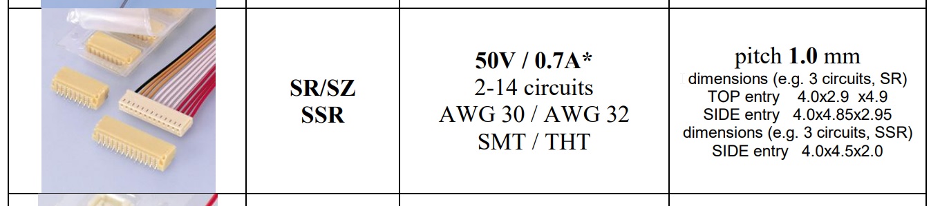
- The dimensions of the housing
- The distance between each pin - AKA the “pitch”
The fundamental outcome of getting this wrong is that you:
- Wind up with a plug that just doesnt fit into a socket,
- Out of pocket a few dollars, &
- Waiting another month for AliExpress to ship you the correct parts
We also DON’T want to get this wrong - it’s inconvenient.
Matching the connector
As explained, matching the pins on the peripheral to the pins on the board is very important to get right, as a mistake could be disasterous.
Matching the connector form factor is less important, as if you mess up, at least you don’t break anything (usually).
Fortunately, matching the pins was (in this instance) a fairly easy process. The form factor took more work.
Matching the pins
It’s time to start searching for AMD Wraith Prism cable pictures- Searching this a while yielded this reddit post.
The post is a cry for help in replacing one of their control cables - They’re missing the 4 pin cable on the right, but they still have the 3 pin cable on the left.
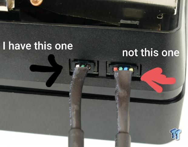
The cable on the left is the one we need to replace. This picture is simple but conveys a lot of information.
In particular, we can see 3 colours on the cable, white, green, and black.
These colours are significant, as they are well documented in the USB2 standard, but to be safe, let’s review another post on the matter.
Reddit user OutrageousOkona asks: Found in my cable drawer, what’s the smaller connector and what could it connect to a usb header? Thanks!
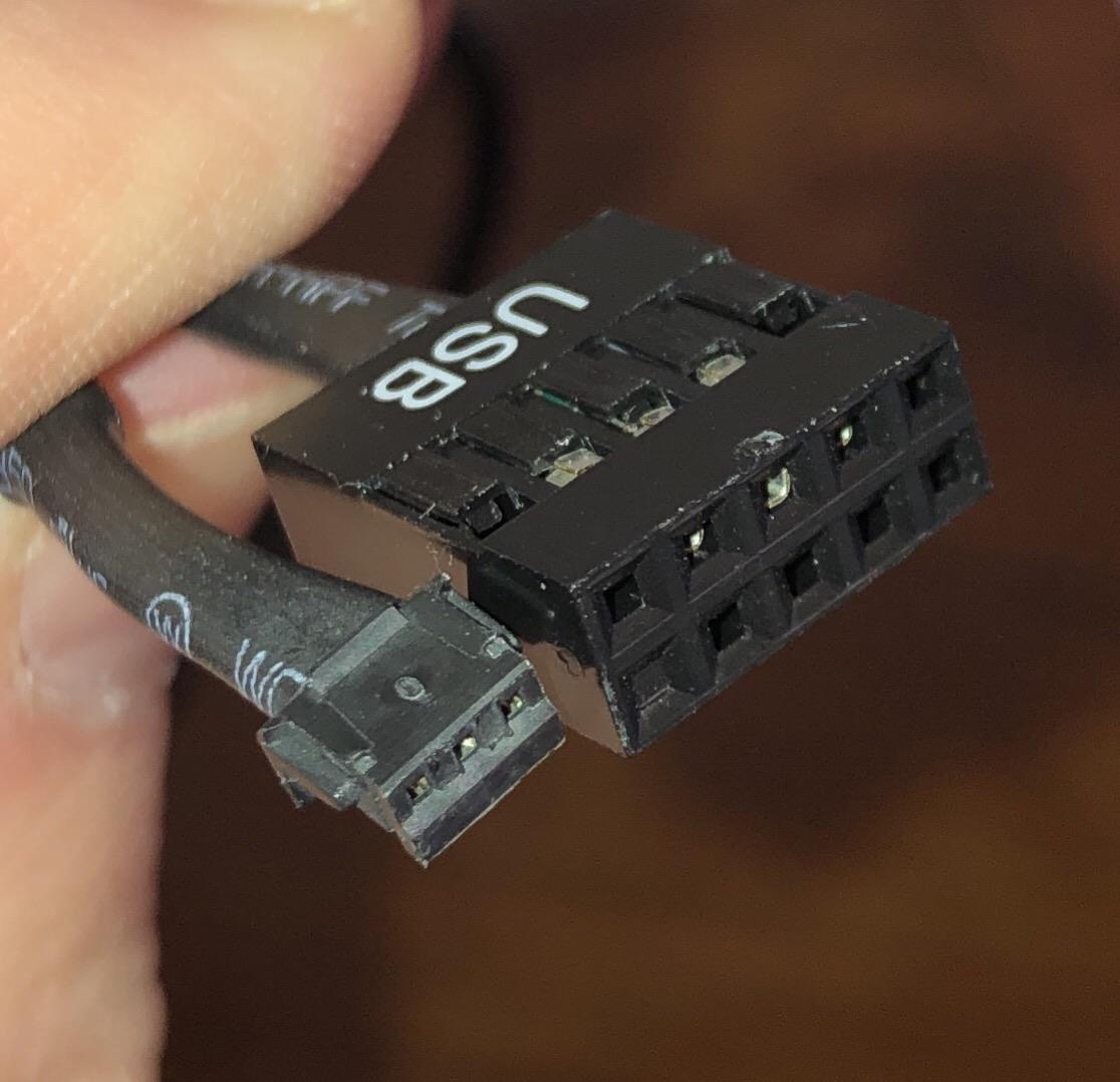
He gives us some excellent closeups (Which I will use for form factor), and commenters seem to think it matches, though oddly enough, OP doesnt own an AMD Wraith Prism:
it looks like the connector for the AMD Wraith Prism Stock Cooler.
It does rather, I don’t own one though. Serves me right for not making a note of it ages ago.
Let’s take note of the other side, though. We can see a 9 Pin USB2 female header cable. Take note of the colours on the 9 pin connector- We can see green is just visible for the middle socket.
It’s hard to say for sure, but it also looks like white might be visible for the rightmost connection.
Is there any way to verify this configuration? Well, fortunately this is very well documented as a convention in the USB2 standard - frontx.com agrees
We now have enough information to comfortably know what line connects to what on each side, and as long as we align our connector correctly, we’re most of the way there.
Matching the form factor
Now is the harder part - determining the form factor of the unknown connector.
The number of pins is trivial - The rest is not.
False starts
Unfortunately, OP’s estimates for the width of their connector were off by enough that the conclusions drawn from them were all incorrect.
In the above post, OutrageousOkona was helpful enough to prove an album with multiple, good quality pictures of the part - as well as a rough measurement for the 3-pin side connector:
it’s just over 4mm wide if that helps.
Estimating the width to be ~4.10mm, I put the picture into GIMP & built some measurement annotations -
I explain how to do this in How to annotate any image with accurate dimensions using free, open-source GIMP.


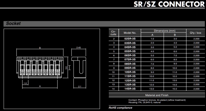
From this, I got a pitch of around 1.05mm - This is on the smaller end for this kind of connector, but, from cross-checking with the JST Product Overview, this appeared to be a reasonable match for the JST SR/SZ
Right after I ordered a set of these, I got a reply on my own request for more info:
The image shared had a very clear reference for dimensions, & very clearly indicated that my original reference was way off.
Actual Dimensions:
yeah yeah, my phone’s camera suck 🙄
Is this what you wanted?

Following the steps described in my other post, I got the following:
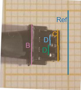
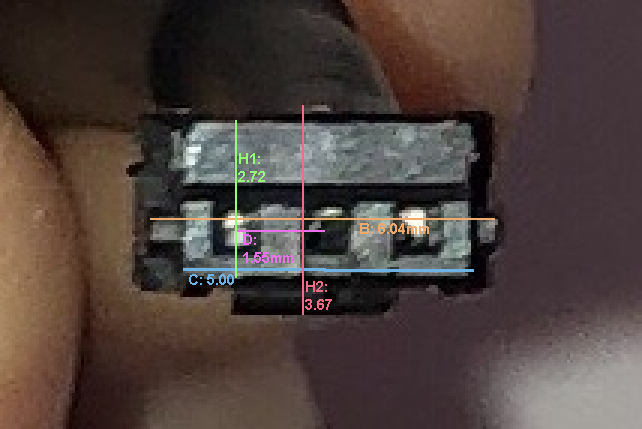
Where:
Ref=10.00mmB≈6.04mmC≈4.9mmD≈1.5mm
Comparing this to the product entry for the JST-ZH3, we see
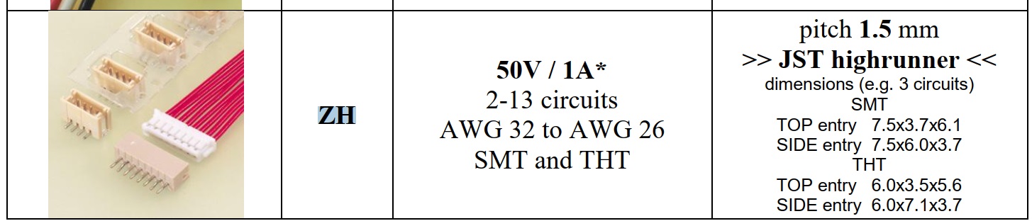
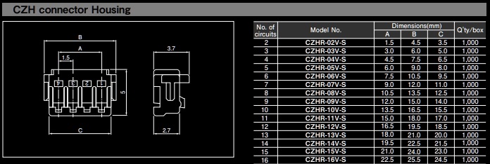
Looks like we have a match!
Building the new connection
Now we need to buy stuff, and make a new connection.
On the motherboard, the corresponding USB2 header has 9 pins, with a standard pitch of 2.54mm (1/10 inch)
Essentially, any female 2.54mm dupont header can connect to the motherboard’s USB header, and all we need to make this work is:
Buying the parts
The Cables
Two cables:
- AMD Wraith
(JST-3ZH-1.5)->Female Dupont- This will plug into the next cable, which we’re using as an “extension” cable
Male Dupont -> Female Dupont, “extension” cable- This extends the first cable, and plugs into the MoBo’s USB2 header
The reason for using the “extension” cable is that the precrimped JST connectors tend to have fairly short leads, so likely won’t reach a USB2 header. If your JST connector wires are long enough to reach, then you might not need the extension cable.

The CPU cable
- A precrimped
JST-3ZH-1.5mmconnector (This is sold as the plug, with the 3 wires already crimped & dangling. We’ll have to crimp the loose ends into connectors) - Dupont Connector parts:
- A set of single row 2.54mm dupont shells (With 4 connectors)
- A roll of female dupont terminal pins (These usually sell in a roll of at least 50)
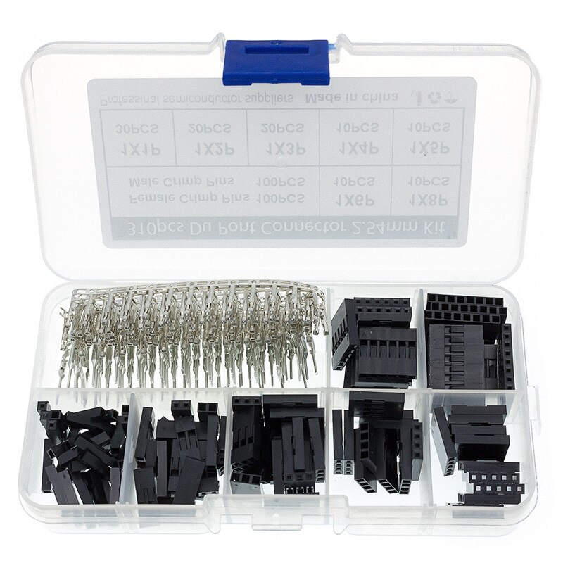
The cheapest & easiest option is to buy a kit, such as this one from AliExpress
The “extension” cable
There are a few options here:
- ✔ Buy generic 4-pin male -> female dupont set
- Buy generic jumpers & crimp your own dupont cables using the kit you already bought
- ❌ Buy a specific USB extension cable (Is colour coded, but can be a bit more expensive)
Option 1 is the easiest.
Certain AliExpress stores will tend to have every part needed - For example NZXIN Store
Example Shopping Cart
- CPU Cable:
- Extension Cable:
Assembling the parts
CPU Cable
We can start by crimping the loose ends of the CPU Cable.
These don’t tend to have much exposed wire, so you may need to strip it a bit more. If you have a dupont crimping tool, then you should use that, but this crimp can be done pretty easily with some flat pliers. Dan Murphy’s Youtube Tutorial demonstrates this.
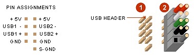
It’s important that we correctly match our pins, the following image demonstrates how
As you can see, there’s an extra socket in our dupont connector that’s not connected to anything-
that’s the 5V power supply line.
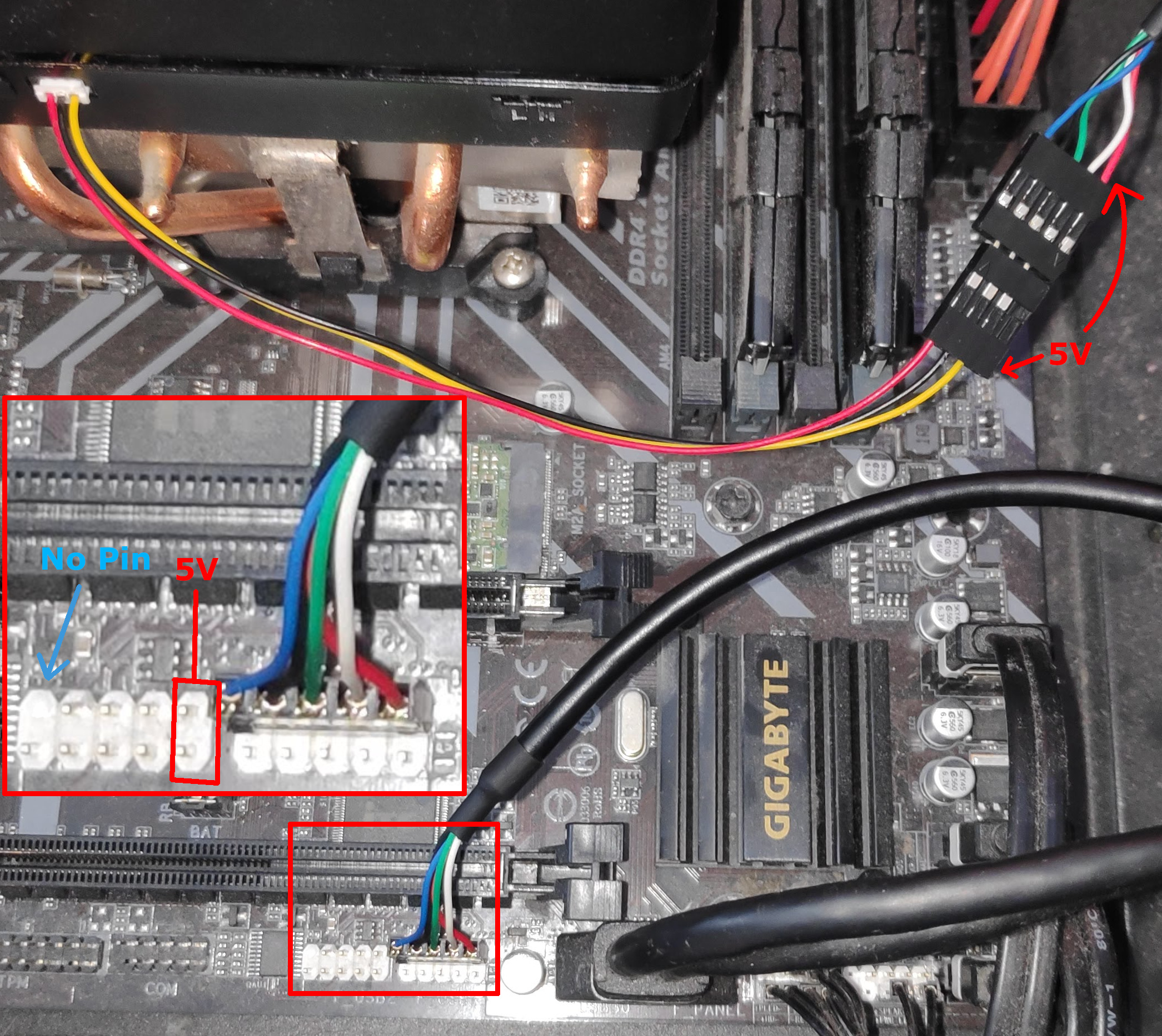
USB2 Alignment
Now, we can plug this into our extension cable, or directly into the USB2 header.
We have to take care to align this correctly with the header.
The header has two rows of USB pins:
- one row has 4 pins:
MISSING,GND,D+,D-,+5V
- one row has 5 pins:
S-GND,D+,D-,+5v
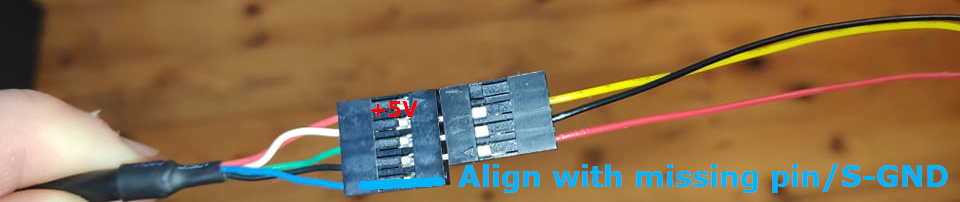
We can tell the alignment by the corner with the missing pin:
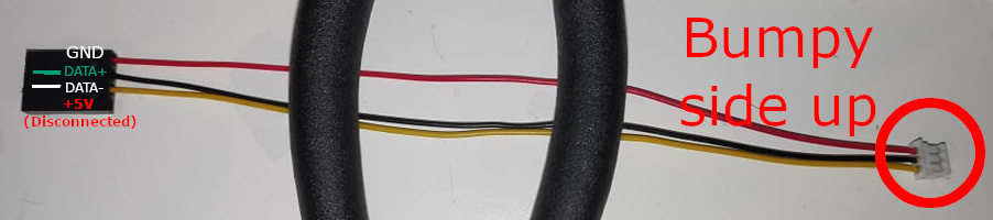
Remembering that on our cable, the +5V pin is disconnected
We have to align it so that the +5V pin goes to the opposite corner from the missing pin.
The following images demonstrate this:
 Color Coded Extension Cord